CAD Files
The generation of a CAD file is one of the most important parts of any CFD simulation. CONSELF can handle multiple geometry types in order to help the user during his task. At the same time, it is recommendable to follow some basics tricks in order to be confident about the final result of the simulation and avoid geometry errors and mesh inconsistencies.
Create fluid volumes
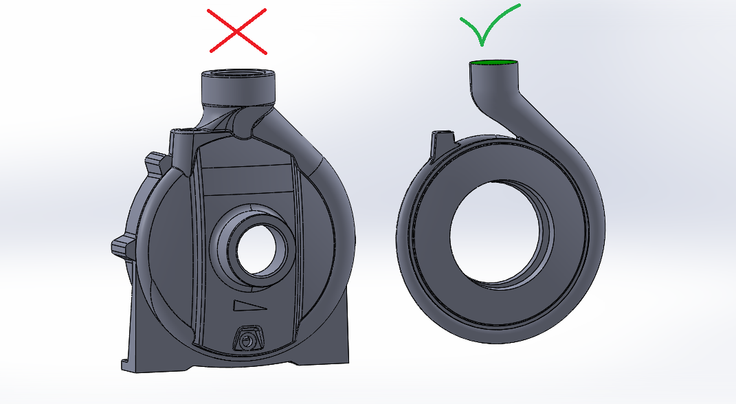
In order to run a CFD simulation you have to generate the volume of fluid. In other words you have to model the geometry occupied by the fluid and not by the solid. Compared to standard modelling, CFD usually requires the negative of the solid model. The picture shows a pump diffuser solid model (incorrect) compared against its fluid model (correct for a CFD simulation).
Simplify your geometry
Remove all features and edges which are smaller than 0.1% times the maximum size of your 3D model. The picture shows a car park with particulars - flanges - which are much smaller than the volume inserted. Because of this, it is a common habits to simplify the geometry - by elimination - all the smallest elements and particulars.
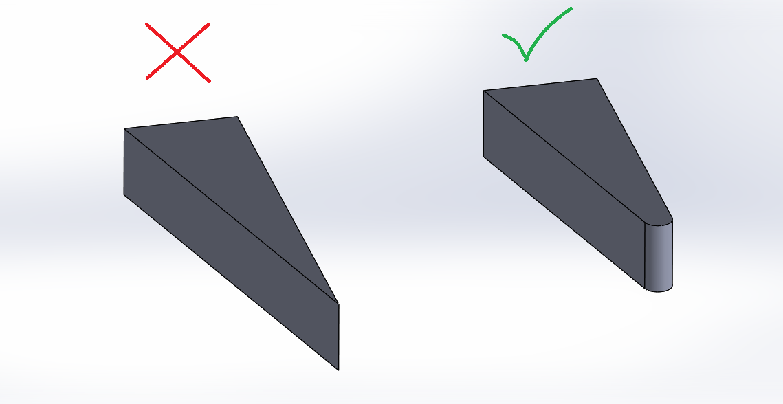
Avoid edges
Avoid narrow angles by creating fillets with a radius of, at least, 0.1% times the maximum size of your 3D model. Very often, this CFD restriction is also a structural problem when actually making the prototype.
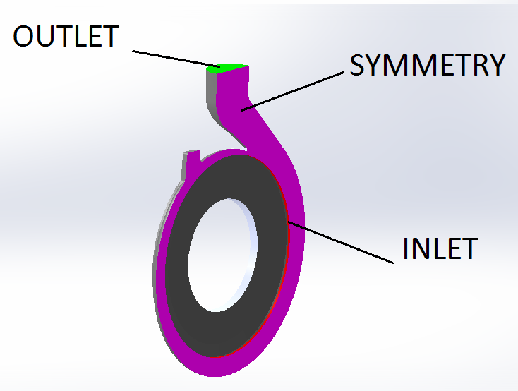
Colors are helpful
Define colors carefully as they help you when applying boundary conditions. In the picture an example of three colors: with them it is possible to define different meshing and CFD parameters on different surfaces. CONSELF also handles different type of boundaries (based on surfaces) by selecting the appropriate option in the GEOMETRY step.
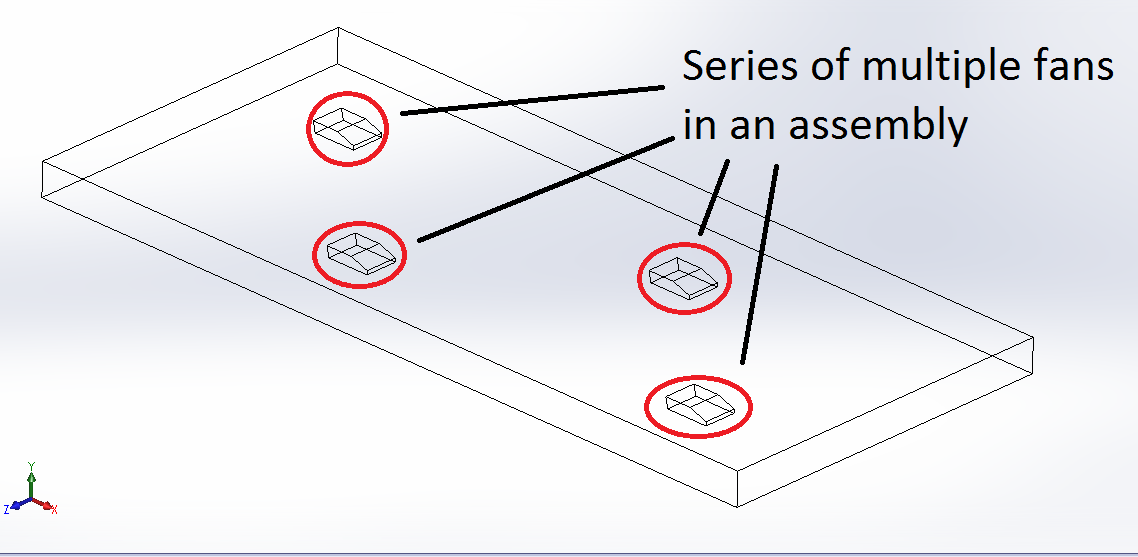
Use assembly for multiple elements
CONSELF also accepts assembly STEP files - very useful to use in case you have multiple object with the same shape or series that share boundary conditions. Remember that, also for assembly, you need to specify the fluid volume. N.B. The boolean operation (i.e. removing the jet fans volume from the room volume) is automatically performed by the GEOMETRY step.